| [ Team LiB ] |
|
2.4 Use Case DiagramsA use case diagram is the highest level of abstraction available in UML. Use cases are collections of related activities that work toward a particular goal. They're part of the requirements gathering process rather than the design process itself, and can be as detailed or as generic as is necessary to communicate system requirements. The challenge here is often to make the requirements accessible and useful to both the design team and the domain experts involved in the project. Depending on need, the size of the team and the preferences of those leading the development a project might have two or three use cases, or dozens, or even more, although there is generally a point at which the sheer volume of use cases grows unmanageable. A "Buy Groceries" use case, for example, could consist of selecting food, checking out, processing a credit card, and bagging groceries. The use case can also incorporate internal variations, such as a declined credit card. Use cases incorporate multiple actors, which may be humans or systems. The actors in the Buy Groceries use case could be the shopper, the checkout person, the grocery bagger, the inventory system, and the credit processor. Like any UML diagram, use cases exist to convey information. A use case diagram can be a valuable communication tool, and the process of creating the use cases themselves almost invariably leads to better software and greater accountability. In addition to ensuring user needs are met, use cases help determine where a system is likely to need extension in the immediate futureinformation that can play a valuable part in the design process. The ultimate consumer of the use case diagram is a human being; as a result, the diagram's goal is clarity, rather than precision. Some developers don't like using use case diagrams at all, preferring text, and some mix-and-match according to the needs of the current project. Use case diagrams at a high level are often used to quickly communicate the scope of a more detailed and nuanced textual discussion. In fact, UML use case diagrams alone are almost, but not quite, useless without the full textual use case sitting behind them. In a diagram, a single use case is represented in the UML with an oval (see Figure 2-1). Detail is added by breaking each use case into a set of smaller use cases and adding them to the diagram. Actors are represented by stick figures. UML use case diagrams are not generally designed to demonstrate sequence. Activity diagrams, discussed later in this chapter, provide a more formalized mechanism for showing process, allowing use case diagrams to focus on goals. Figure 2-1. A simple use case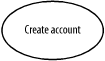 Let's look at a more complex set of use cases. The project is a corporate web portal that will serve employees, customers, and partners. The task at hand is use registration for each type of user. Employees are assumed to be able to register themselves. Customers can, too. Partners can register themselves and get basic access, but need to be checked against a partner list before they can be granted full access. If the partner isn't on the list, a manager needs to authorize partner-level access for the user. We'll use this example (or variations) throughout this chapter. To begin, we divide the problem into four basic use cases: Request Account, Define Partners, Approve Account, and Create Account. A simple UML diagram, as in Figure 2-2, shows the three actors that interact with the use cases. Figure 2-2. Use cases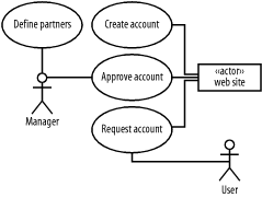 The actors, represented by stick figures, are connected to the use cases they are involved with. The Manager and User actors are humans. The web site is not, so we represent it as a box. The box contains the notation «actor». This string, like all text encased in guillemots, is called a stereotype, and "overrides" the standard behavior of any shape in the UML. In this case, we identify a box (which usually indicates a class or an objectsee Figure 2-2) to mark it as an actor. From a use case diagrams perspective, there is no difference between a stick figure and a stereotyped box, but using both forms lets us distinguish between people and systems. It stands to reason that each user category has a different kind of account, since partners, customers, and employees have different data associated with them. Right now it doesn't matter whether we implement these accounts as three different classes (presumably descended from the same superclass), or as a single class with a wide variety of fields. From a use cases perspective, the process of requesting an account breaks down into three use cases. Each case is a subtype of the Request Account use case, and we represent it using the generalization relationship, identified by an open-headed arrow (Figure 2-3). We don't have to show every actor, as the diagram would rapidly grow cluttered. Figure 2-3. Generalized use cases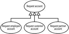 We can also use generalization on actors, so employees, customers, and partners can generalize to users. When a use case includes multiple other use cases, an include relationship, indicated by a dashed arrow and an «include» stereotype, can be used to diagram the interaction. If a company assigns a value to a customer based on credit history and purchase history (for instance, in a loyalty program), the use case diagram for the activity might look like the one in Figure 2-4. Figure 2-4. Included use cases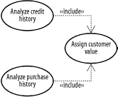 If a use case includes child use cases (in the example above the analysis use cases include the Assign Customer Value use cases) it might not be complete otherwise. The inclusion construct makes it easier to expand or contract use case diagrams according to varying requirements. A high-level diagram might simply include the Assign Customer Value use case, requiring the reader to investigate further in order to determine exactly what that particular use case consists of. Use cases can also be extended by other use cases. In that kind of situation, a main use case declares one or more extension points. Extension points identify instances in the use case in which functionality from other use cases can be included. The extending use case declares the additional functionality and is connected to the main use case by an arrow and an «extends» stereotype. In Figure 2-5, an Authorize User use case declares an extension point for access approval. If the user being authorized is an employee or a partner, the use case can use the logic in the Employee Authorization and Partner Authorization use cases. Unlike use cases that incorporate other cases via the include functionality, the base use case should be complete whether or not any extensions exist. Figure 2-5. Extending use cases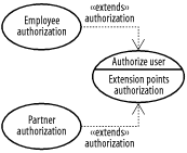 |
| [ Team LiB ] |
|